Modular refining · 500 to 20,000+ bpd

Refine your own crude
where you produce it.

Modular vacuum-distillation units, engineered and built by our own team, sized to each project.

Isometric scene of a modular refinery on its site: two crude storage tanks on the left feed the modular vacuum-distillation unit in its two-level steel structure; naphtha and diesel leave through one header and heavy cuts through another to two product tanks on the right; a tank truck loads at a loading island in front. Everything on one concrete pad.
A 2 + 1 unit on its site · schematic

For · State oil companies · Energy ministries · Operators and refiners

The reality today

Producing crude and buying the fuels abroad.

The crude leaves the country and the fuels come back refined. In between sit the freight, the international logistics and an import price that moves with geopolitics.

  1. 01

    Every barrel travels twice

    It leaves as crude and comes back as fuel. The transport, insurance and logistics both ways are paid by the producer.

  2. 02

    Prices nobody controls

    Imported fuel is priced in distant markets. A conflict thousands of kilometres away changes the price at the pump.

  3. 03

    Expanding a refinery takes years

    A conventional expansion is a multi-year, capital-heavy project. Demand does not wait.

  4. 04

    Residues that could be fuel

    Residuals, used oils and condensates that could be diesel or fuel oil are sold as waste, or paid to be disposed of.

The technology

A two-stage process train, configured to your crude.

Multi-stage vacuum distillation. The feed enters at one end; each tower delivers its cut and passes the rest on.

Configurable train in its steel structure: one rising-film and one wiped-film tower drawn solid as the base, and the towers that can be added, up to three and up to four, dashed. Railed platform, condensers, receivers, pumps, cabinets and heater. Feed from the left; naphtha and diesel through one header and heavy cuts through another, on the right.

Solid towers are the base; dashed ones are added according to the products the project needs.

The unit separates; it does not crack or desulphurise. Cuts are named by their range and final quality is confirmed with the characterisation of each feedstock.

Stage 011 to 3 towers

Rising film

The light cuts: naphtha and diesel. A thin film of product rises along heated tubes under vacuum, and the light fractions evaporate at a lower temperature.

Stage 021 to 4 towers

Wiped film

The heavy cuts: gas oils, fuel oil, lubricant bases and asphalt. A rotor spreads a film on the heated wall, under deeper vacuum, without cracking the product.

  • Each tower, independent

    Its own vacuum and its own heating per tower. If one stops, the others keep producing.

  • Indirect heat by thermal oil

    No flame touches the product. Temperature is controlled per tower.

  • One control

    One temperature loop and one vacuum loop per tower; one PLC and one screen with recipes, alarms and interlocks for the whole unit.

  • Stainless steel, in modules

    Stainless construction, delivered as skid-mounted modules and assembled on site.

Configured to measure

Three towers to start. More towers for more specific products.

How many towers a train carries depends on the products the project needs and what they will be used for.

Modular vacuum-distillation unit in its two-level steel structure: 2 rising-film towers and 1 wiped-film tower pass through the railed platform; a condenser beside each tower; receivers, pumps and control cabinets below; the thermal-oil heater with its stack to one side. Feed enters on the left and the products leave through two headers on the right.
2 + 1Recommended

To start

Naphtha, diesel and heavy oil. The recommended configuration for a first unit.

Modular vacuum-distillation unit in its two-level steel structure: 2 rising-film towers and 3 wiped-film towers pass through the railed platform; a condenser beside each tower; receivers, pumps and control cabinets below; the thermal-oil heater with its stack to one side. Feed enters on the left and the products leave through two headers on the right.
2 + 3

With specific oils

Adds gas oils and lubricant bases to the fuels.

Modular vacuum-distillation unit in its two-level steel structure: 3 rising-film towers and 4 wiped-film towers pass through the railed platform; a condenser beside each tower; receivers, pumps and control cabinets below; the thermal-oil heater with its stack to one side. Feed enters on the left and the products leave through two headers on the right.
3 + 4

Complete train

Every cut, from naphtha to asphalt, in one unit.

rising film + wiped film

A 500 bpd pilot unit proves the yields on a single stream before scaling. The configurations are references, not a closed catalogue.

What goes in

  • Light and heavy crude
  • Condensates
  • Residuals
  • Used oils

What comes out

  • Naphtha
  • Diesel
  • Gas oils
  • Fuel oil
  • Lubricant bases
  • Asphalt

What each tower yields depends on the feed; the train is configured for the products of the project.

In numbers

500 to 20,000+ bpd
per unit, sized to the project
1–3 + 1–4 towers
per process train
4 to 6 months
of fabrication
45 to 90 days
of installation on site
40+ years
of the team in the energy industry
100 % stainless
in construction

It already exists

Units built, installed and in operation.

With clients in the United States and Colombia. Names are withheld for confidentiality.
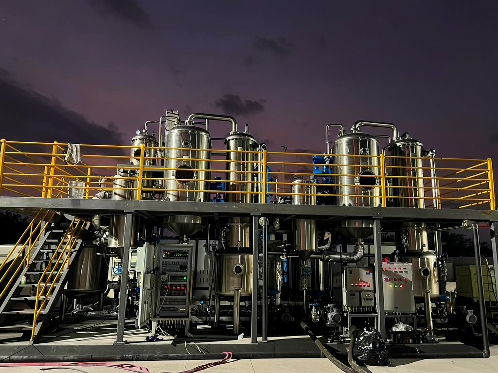
  • Modular distillation unit in operation, at night.

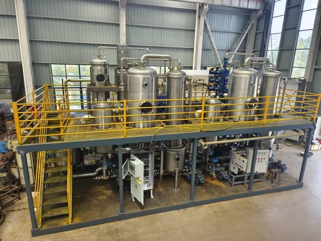
    Unit in operation

  • Complete unit assembled inside the fabrication hall.

    Complete unit in our factory

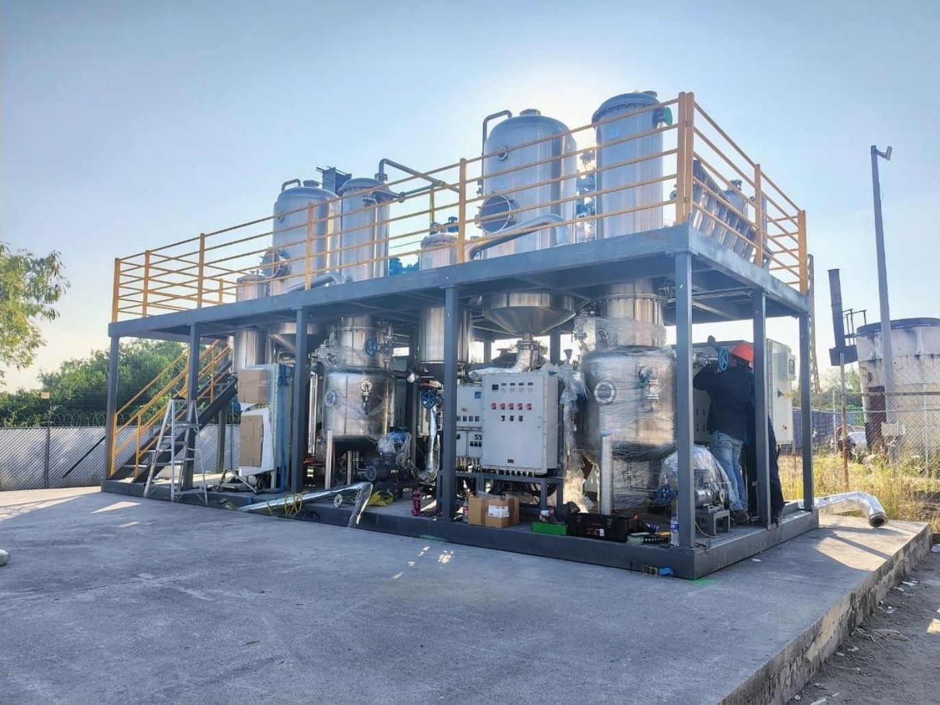
  • 500 barrel-per-day plant installed at the client site.

    500 bpd plant on site

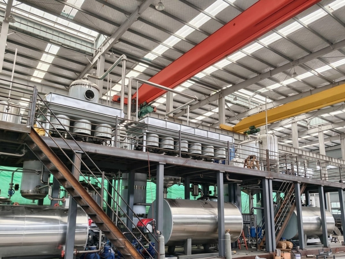
  • Process train of about 3,000 barrels per day in fabrication.

    ~3,000 bpd train in fabrication

Own engineering and manufacturing

Every unit is designed, built and tested in our own facilities.

From the 3D model to delivery in modules, the same team carries the unit from start to finish.
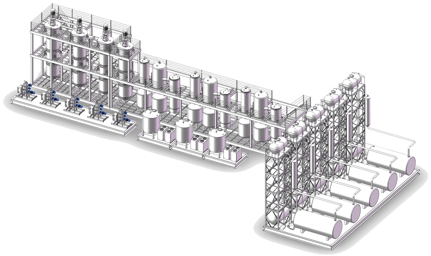
Isometric 3D model of a modular distillation unit.

Every plant, modelled in 3D

The whole unit is modelled before steel is cut: equipment, piping, skids and access.
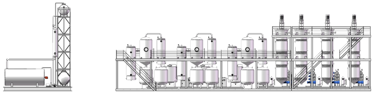
Process elevation drawing of the distillation train.

Process elevation

Towers, exchangers and pumps in the elevation of the train, with the real heights of the site.
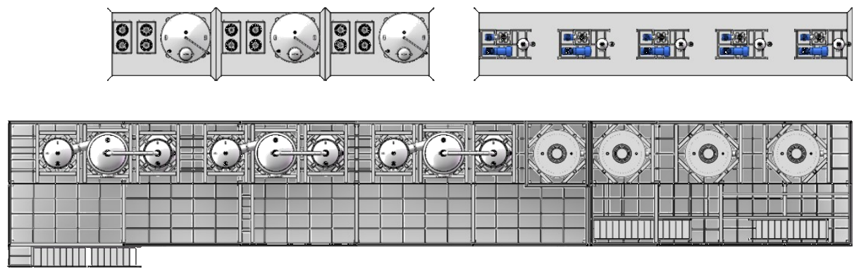
Plan view drawing of the modular unit on its site.

Plant layout

The plant on its ground: modules, tanks and circulation, drawn for the client site.

Delivered in modules

Fabrication in 4 to 6 months. Installation on site in 45 to 90 days. Capacity for about ten units a year.

Why the cost is different

No intermediaries between the design and your site.

The price of each unit is set per project. What does not change is the structure that makes it possible.

  • Own engineering

    The design is not subcontracted. We control the specification, the quality and every iteration.

  • Own manufacturing

    We build in our own facilities, with no intermediary or integrator margin.

  • Standardised design

    The reference configurations share components: fewer spares and a shorter start-up.

  • Direct delivery

    From the workshop to the site, with our own installation and commissioning team.

Where it applies

Three places where a modular refinery changes the math.

  • Oil and refining

    Refining capacity next to the well, the field or the terminal, without waiting for the central refinery to expand.

    • Heavy crudes and residuals as feedstock.
    • Diesel and naphtha for distribution.
    • Added capacity without building a conventional refinery.
  • Power and industry

    Own fuels for power generation, mining and industrial processes that buy them today.

    • Fuel produced on site, next to the plant that burns it.
    • Fuel oil and diesel for generation.
    • Stable demand, close to the point of use.
  • Used oils and residues

    Residuals, used oils and condensates turned into diesel, fuel oil and lubricant bases.

    • Re-refining of used lubricating oil: industrial, transmission, hydraulic.
    • Refinery bottoms, sludges and process tails turned into fractions with value.
    • Thermal and dielectric oils as feedstock.

How we start

What we need and what you receive.

With the feedstock, the cuts and the site defined, Refinnova delivers the unit configuration and the economic proposal.

What we need

  1. 01Feedstock characterisation: a crude assay or an analysis of the oil or residue.
  2. 02The cuts and products wanted, and their destination.
  3. 03Required capacity, in barrels per day.
  4. 04Site and available utilities: tanks, power and fuel.
  5. 05A technical counterpart.

What Refinnova delivers

  1. →Train configuration: number of towers and conditions for that feedstock.
  2. →Unit design, with estimated yields.
  3. →Fabrication and installation plan, with dates.
  4. →Economic proposal.

Next step

Tell us about your project.

With your crude, your capacity and your site, we propose the train configuration and the next steps. No commitment.

Your data is used only to reply to you. Privacy notice